Sneak Circuit Analysis (SCA) is a technique used in engineering to identify and analyze unexpected or unintended circuit paths in electronic systems. These paths are known as "sneak circuits" and can cause errors or malfunctions in a system, leading to potential safety hazards or damage to the equipment.
SCA involves examining a system's design, identifying potential sneak circuits, and then simulating how they could operate under different conditions. This analysis can help engineers to identify potential issues and make design changes to prevent sneak circuits from occurring.
Sneak circuits can occur due to a variety of factors, such as incomplete designs, component failures, or interactions between different parts of a system. By performing SCA, engineers can identify and mitigate these issues before a system is deployed, improving its reliability and safety.
Sneak Circuit Analysis plays a critical role in ensuring the safety of electronic and electro-mechanical systems that are safety-critical. These systems may be susceptible to sneak conditions, which are latent conditions in hardware, software, or integration that can cause unwanted actions or prevent desired functions without any component failure.
SCA is a method used in safety-critical systems to detect hidden paths or sneak circuits that could lead to unwanted actions or inhibit desired functions. It involves identifying design flaws that allow sneak conditions to develop and is distinct from other system analysis methods because it focuses on detecting designed-in inadvertent modes of operation rather than failed equipment or software. By using SCA, engineers can prevent potential issues and improve the reliability and safety of these systems.
SCA is most applicable to circuits that can cause irreversible events. These include:
- * Systems that control or perform active tasks or functions
- * Systems that control electrical power and its distribution
- * Embedded code which controls and times system functions
Sneak conditions are classified into four basic types:
- 1. Sneak paths - unintended electrical (current) paths within a circuit and its external interfaces.
- 2. Sneak timing - unexpected interruption or enabling of a signal due to switch circuit timing problems which may cause or prevent the activation or inhibition of a function at an unexpected time.
- 3. Sneak indications - undesired activation or deactivation of an indicator which may cause an ambiguous or false display of system operating conditions.
- 4. Sneak labels - incorrect or ambiguous labeling of a switch which may cause operator error through inappropriate control activation.
Typically Sneak Circuit Analysis has been advocated by the defense and aerospace communities and current standards and guidelines include NASA's Sneak Circuit Analysis Guideline for Electromechanical Systems (PD-AP-1314) and AIAA's Performance-Based Sneak Circuit Analysis (SCA) Requirements (BSR/ANSI/AIAA S-102.2.5-2xxx).
Sneak Circuit Example
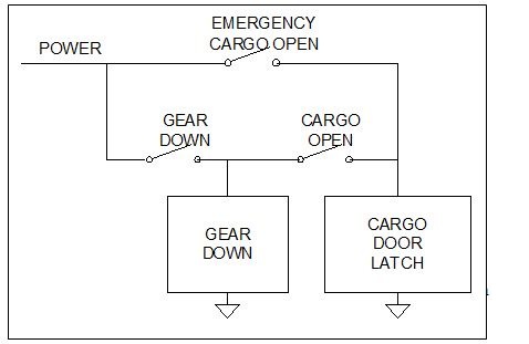
Sneak circuit analysis can be illustrated with a simple example involving an aircraft cargo door release latch. The normal cargo door control is designed to prevent unintended opening of the door in flight by being powered in series with the GEAR DOWN switch. However, in the event of an emergency, an EMERGENCY CARGO OPEN switch may be used to release the latch. If the flight personnel try the normal switch first and then use the emergency switch without reopening the normal switch, it can cause the landing gear to lower unexpectedly. This is a sneak circuit, which can be identified and prevented through proper analysis techniques.
Two observations about this sneak circuit apply generally:
- 1. Switches or other control elements are operated in an unusual or even prohibited manner
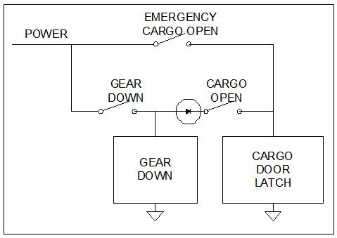
- 2. The unintended function (in this example the lowering of the landing gear) is associated with current flow through a circuit element that is opposite to the intended current flow.
The latter of these conditions permits elimination of the sneak circuit by inserting a diode as shown:
See Also:
ALD Reliability Prediction Software
ALD Reliability Analysis and Safety Assessment Software
Download ALD Reliability&Safety Software


