
Fault Tree Analysis (FTA) Technical Methodology & Mathematical Foundations
An advanced technical reference detailing deductive fault tree modeling, Boolean logic operations, Minimal Cut Set (MCS) algorithms, and probabilistic calculation standards within Safety Commander.
What is Fault Tree Analysis (FTA)?
Fault Tree Analysis (FTA) is an indispensable top-down analytical method that uses Boolean logic diagrams to model how various component failures, operational errors, and environmental conditions combine to cause a critical system failure.
Essential to safety and reliability engineering, FTA helps technical teams uncover hidden failure vectors, prioritize risk mitigation strategies, and accurately quantify accident probabilities across hardware, software, and human interactions.
Widely adopted in aerospace, defense, nuclear power, chemical processing, automotive, and other high-hazard sectors, fault tree structures convert seamlessly into probabilistic models—delivering exact failure rates and system importance metrics required for strict industry compliance.
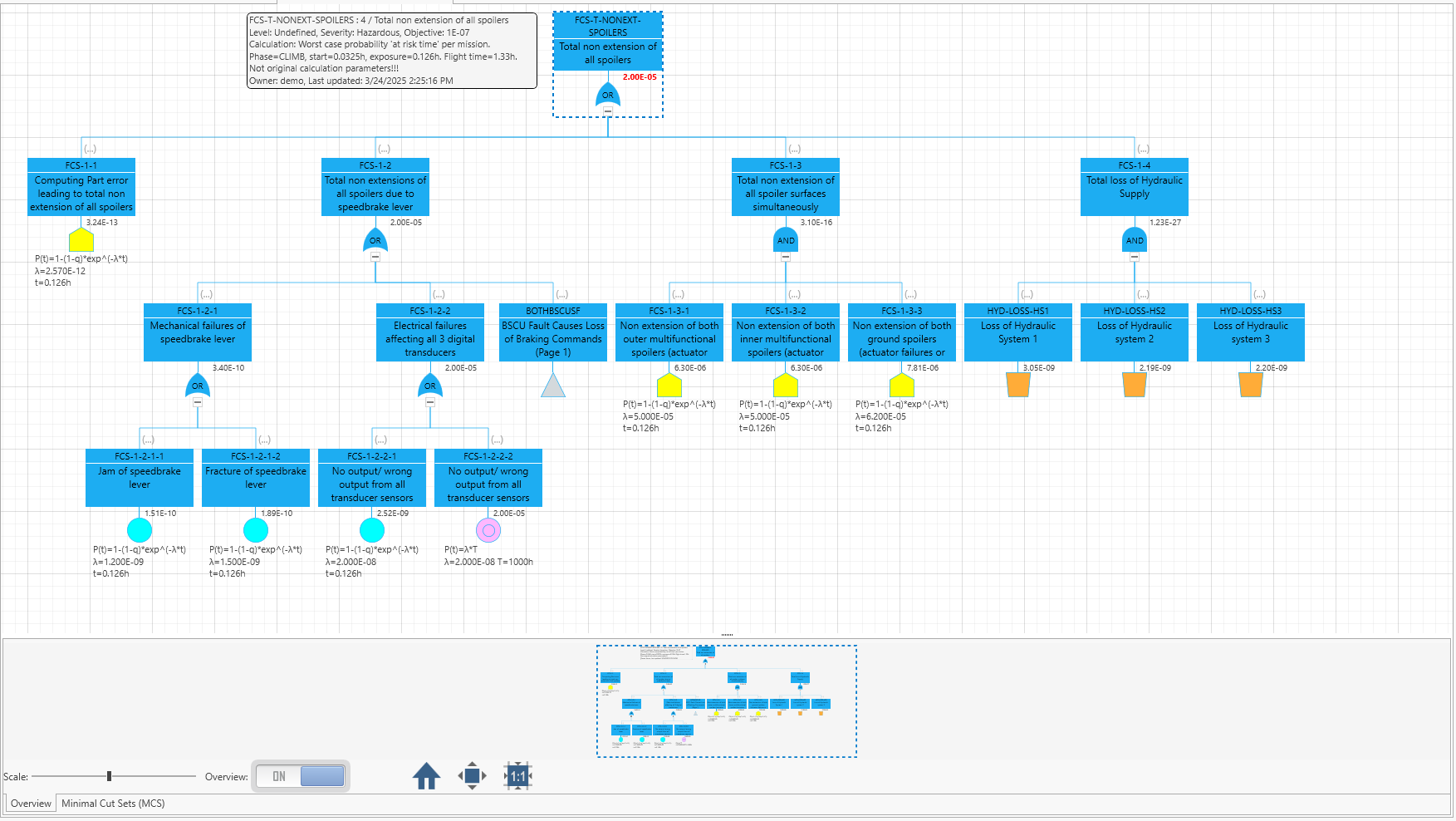
Quantitative Calculation Reference Formulas
Below are the underlying probability formulas applied during gate evaluation and importance calculations in Safety Commander:
Minimal Cut Set (MCS) & Importance Verification
During system assessment, raw fault trees undergo Boolean reduction to generate Minimal Cut Sets—the smallest combinations of basic failure modes capable of triggering top-level hazard states.
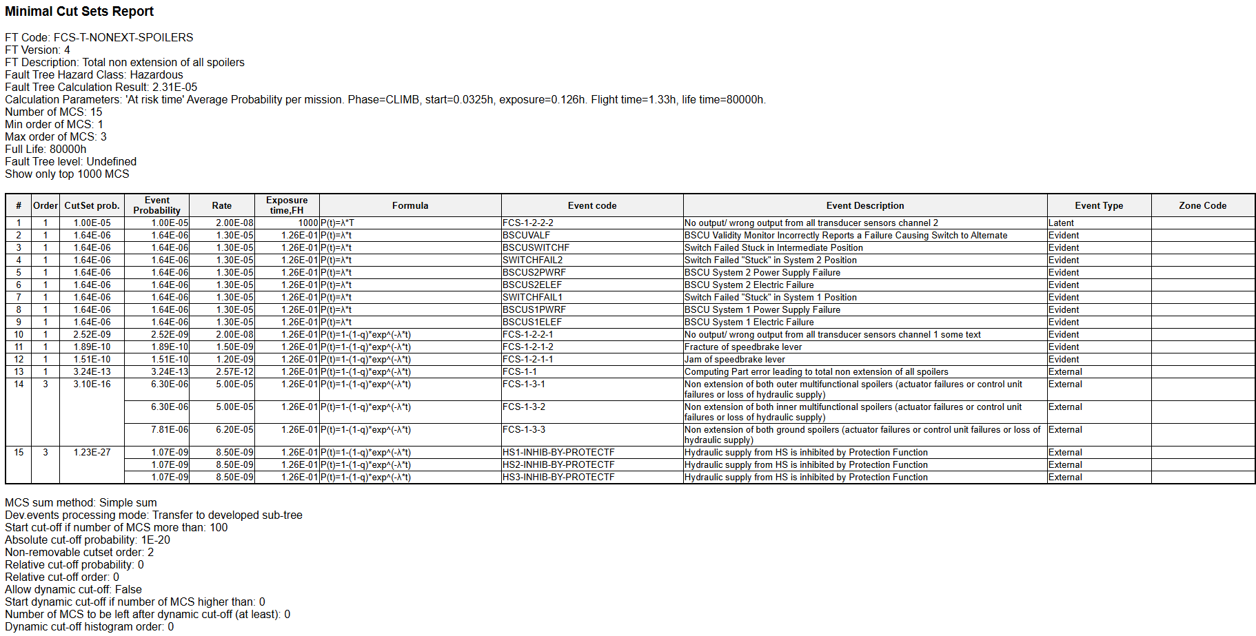
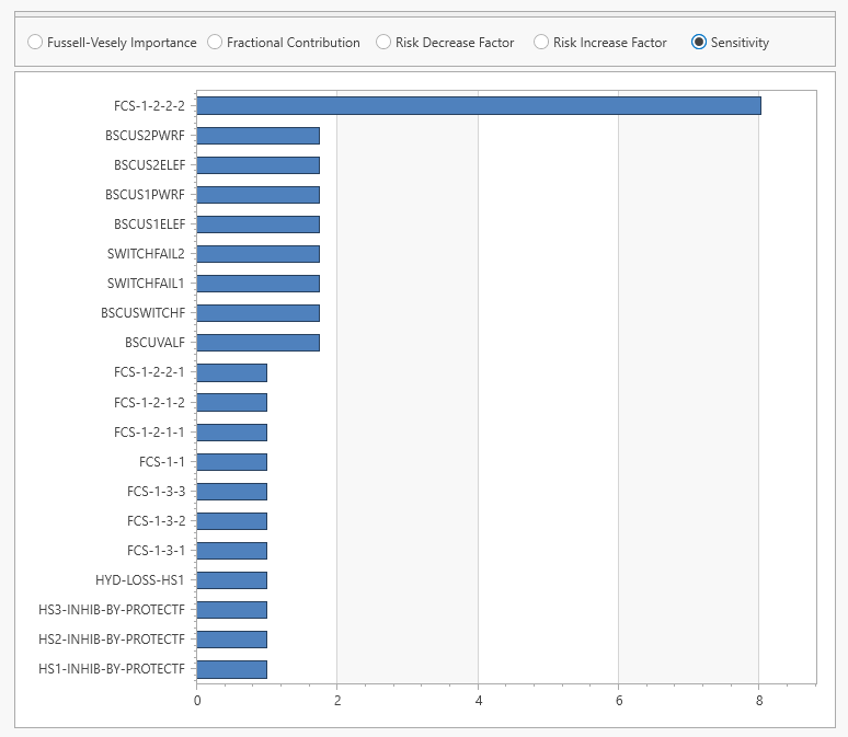
Following cut set extraction, Safety Commander ranks basic event criticality using Fussell-Vesely (FV), Risk Achievement Worth (RAW), and Risk Reduction Worth (RRW) indices.
Verification & Mathematical Execution Process
Methodological sequence for verifying complex fault tree models.
Define top event conditions and construct logic gate pathways.
Transform gate hierarchies into disjunctive normal forms.
Apply probability cutoffs to eliminate negligible failure paths.
Compute exact top-level unreliability and availability metrics.
Evaluate Fussell-Vesely and RAW indices for component isolation.
Technical Execution Features
Advanced mathematical features supporting large-scale safety modeling in Safety Commander:
- Multi-System Dependencies: Integrates shared events across sub-system architectures.
- Automated FMECA Linkage: Imports failure rates directly from RAM Commander FMECA modules.
- OPSA Standard Compliance: Supports open-format model interchange for MBD environments.
- Cycle & Loop Resolution: Handles circular logic dependencies automatically during Boolean reduction.
Supported Engineering Guidelines
Formal verification standards enforced across safety-critical domains:
Technical FAQ & Calculation Methodologies
How are Minimal Cut Sets calculated in probabilistic safety assessments?
Minimal Cut Sets (MCS) are evaluated by expanding gate logic expressions into disjunctive normal form using Boolean algebra algorithms, isolating the smallest combinations of basic events capable of causing top event failure.
What is the difference between worst-case and time-averaged unavailability in FTA?
Worst-case unavailability evaluates peak probability at maximum operational mission duration T, whereas time-averaged unavailability models mean failure probability across periodic maintenance inspection intervals.
How does Safety Commander manage Cut Set Truncation?
Safety Commander applies probability cutoffs and order-based truncation limits during Minimal Cut Set evaluation to exclude negligible risk contributions without compromising system accuracy.