
A comprehensive process-to-module mapping for civil aircraft safety certification. Aligned with SAE ARP4761A and Safety Commander Collaborative Enterprise Edition.
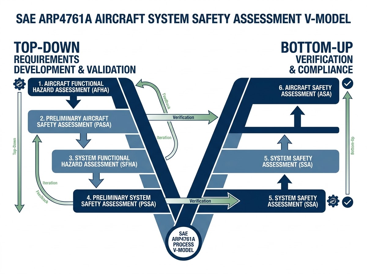
The safety assessment process defined in SAE ARP4761A is highly iterative and fundamentally integrated with the system-level engineering V-model of ARP4754B. It establishes the quantitative and qualitative proof required to substantiate that civil airborne systems are fail-safe. In modern aerospace development programs, managing these mammoth safety tasks across multi-vendor, multi-disciplinary teams is a critical challenge. Safety Commander provides a robust, model-based design database environment to execute these requirements traceably, bridging the gap between standard guidelines and day-to-day safety engineering activities.
The safety assessment process in ARP4761A is divided into six principal phases, flowing systematically down from aircraft functions to itemized engineering designs, and verifying safety objectives upward in hardware/software:
Initiated at conceptual design. Systematically identifies failure conditions of aircraft-level functions, determines effects on aircraft/crew/occupants, and assigns severity classifications (Catastrophic, Hazardous, Major, Minor, No Safety Effect) to establish safety objectives.
Evaluates proposed aircraft architecture against AFHA safety objectives. Identifies subsystem interdependencies, assigns Function Development Assurance Levels (FDALs), and derives aircraft-level safety requirements.
Conducted early in system development to identify and classify failure conditions for system-level functions, setting baseline safety objectives regardless of specific hardware/software implementation.
Iterative architecture evaluation deriving lower-level safety requirements. Allocates probabilistic budgets, assigns Item Development Assurance Levels (IDALs) for DO-254/DO-178C, utilizing FTA, Dependence Diagrams, and Markov models.
Bottom-up verification confirming implemented physical designs meet qualitative and quantitative objectives. Relies on hardware failure rate predictions, detailed FMECA records, and quantitative fault trees.
Evaluates the fully integrated airplane. Synthesizes system SSAs and common cause analyses (ZSA, PRA, CMA) to verify that the complete vehicle implementation satisfies all top-level safety objectives.
The complete hierarchical linkage mapping of ARP4761A chapters, safety processes, and mathematical appendices to dedicated functional software modules inside Safety Commander Enterprise Edition:
| ARP4761A Chapter / Appendix | Short Process Explanation | Dedicated Safety Commander Module |
|---|---|---|
| Chapter 1: Scope | Outlines guidelines for conducting aerospace safety assessments to show compliance with certification regulations (14 CFR/CS Parts 23, 25, 27, 29, 33, 35). | Project Settings & Airframe Definitions Module |
| Section 3.2 / Appendix A: AFHA | Aircraft Functional Hazard Assessment. Top-down, qualitative appraisal of aircraft-level functions to identify and classify failure conditions and safety objectives. | AFHA Module (Central Aircraft Database) |
| Section 3.3 / Appendix B: PASA | Preliminary Aircraft Safety Assessment. Systematic evaluation of proposed architecture against safety objectives, assigning Function Development Assurance Levels (FDALs). | PASA Module (Interdependence & Alignment) |
| Section 3.4 / Appendix C: SFHA | System Functional Hazard Assessment. Performed early in system development to identify/classify system-level hazards and establish safety objectives. | SFHA Module (System Function Editor) |
| Section 3.5 / Appendix D: PSSA | Preliminary System Safety Assessment. Iterative evaluation deriving lower-level safety requirements (redundancy, monitors, IDALs). | PSSA Module & Requirements Traceability (IBM DOORS Integration) |
| Section 3.6 / Appendix E: SSA | System Safety Assessment. Comprehensive, bottom-up evaluation verifying that the implemented system design meets quantitative and qualitative safety requirements. | SSA Module (Unified FTA/FMECA Integration) |
| Section 3.7 / Appendix F: ASA | Aircraft Safety Assessment. Final consolidated evaluation of fully integrated aircraft architecture confirming aircraft-level safety objectives are met. | ASA Module & Automated Final Certification Document Generator |
| Section 3.9: FDAL & IDAL Assignment | Guidelines and mathematical combinations to assign development assurance levels to system functions (FDAL) and physical/software items (IDAL) based on severity. | PASA/PSSA Development Assurance Rigor Engine |
| Section 3.10: Considerations of Human Error | Evaluates the influence of human actions, flight crew procedures, and situational awareness on mitigating flight hazard consequences. | Crew Action & Flight Deck Indication Mapping Module |
| Section 4.1 / Appendix G: Fault Tree Analysis (FTA) | Top-down deductive analysis mapping undesired system-level top events down to combinations of hardware, software, or human basic events. | Fault Tree Analysis (FTA) Module (FT Navigator, millions of cut-sets calculation) |
| Section 4.1 / Appendix H: Dependence Diagram (DD) | Alternative reliability block layout to represent system success/failure paths using series (OR) and parallel (AND) block arrangements. | Dependence Diagram Module |
| Section 4.1 / Appendix I: Markov Analysis | State-transition modeling method used to calculate failure probability in complex, time-dependent, and redundant systems with active repair cycles. | RAM Commander Integration Module |
| Section 4.1 / Appendix N: Model-Based Safety Analysis (MBSA) | Uses formal modeling language to build a Failure Propagation Model (FPM) computing failure sequences and cut-sets directly from architecture design. | MBSA Integration Engine (Supports OPSA & MBSE CAD inputs) |
| Section 4.2 / Appendix J: FMEA & FMES | Bottom-up inductive analysis of physical component failure modes and subsequent summarization of their effects (FMES) at higher levels. | FMECA & FMES Module (Unified component database feeding the FTA) |
| Section 4.3 / Appendix O: Cascading Effects Analysis (CEA) | Qualitative bottom-up analysis evaluating sequential functional and physical effects propagation resulting from initiating conditions due to system dependencies. | System Dependencies Graph Module (Cross-system effects visualization) |
| Section 4.4 / Appendix K: Zonal Safety Analysis (ZSA) | Evaluates physical installation safety, clearances, and inter-system interactions within defined physical zones/compartments of the airframe. | Zonal Analysis Module (Multi-user spatial safety checklists) |
| Section 4.5 / Appendix L: Particular Risk Analysis (PRA) | Evaluates system architecture vulnerability to localized or global threats (engine burst, tire burst, bird strike, lightning). | Particular Risk Analysis (PRA) Module (Threat trajectory modeling) |
| Section 4.6 / Appendix M: Common Mode Analysis (CMA) | Structured qualitative review of redundant system designs to verify physical, functional, and development independence. | CMA Checklist & Questionnaire Module (Independence validation) |
| Chapter 5: Safety-Related Maintenance Tasks | Establishes safety justifications and exposure intervals for latent failures, determining mandatory maintenance inspections. | CCMR/Latent Failure Exposure Interval Engine (CMR Management) |
| Chapter 6: Master Minimum Equipment List (MMEL) | Justifies safe aircraft operations with specific equipment inoperative, analyzing worst-case subsequent failure combinations. | Master Minimum Equipment List (MMEL) Module (Automated next-worst failure risk analysis) |
| Chapter 7: Time Limited Dispatch (TLD) | Formulates operating rules and maximum allowable dispatch times with active control faults on FADEC turbine engines. | TLD Engine Analysis Module |
| Chapter 8: In-Service Safety Assessment | Sets up continuous, closed-loop tracking of field anomalies, lessons learned, and continued airworthiness safety events. | FavoWeb FRACAS / Hazard Tracking System (HTS) Module |
All aircraft definitions, flight profiles, FHA hazard classifications, FTA logic paths, FMECA failure modes, and CMA findings are integrated inside a single database. This prevents inconsistent definitions between suppliers and OEMs.
Unlike legacy safety assessment tools, Safety Commander utilizes Binary Decision Diagrams (BDD) to handle immense multi-system fault trees with millions of cut-sets seamlessly, performs accurate average probability calculations, and automatically resolves complex circular dependencies (loop fault trees).
Enables version and revision control for aircraft and system databases throughout the design lifecycle, supporting multi-site and multi-vendor collaboration with role-based permissions.
Unify your ARP4761A AFHA, PASA, PSSA, and SSA workflows into a single collaborative database.